How to Configure the EPCS4SI8N Chip for SPI Communication

Configuring the EPCS4SI8N PLC controller remote I/O device SPI protocol serial configuration chip is essential for enabling devices to share data efficiently. This setup allows the EPCS4SI8N to store and retrieve data seamlessly. Proper configuration ensures smooth operation and prevents issues such as signal errors or corrupted data.
It is crucial to thoroughly check both the hardware and software settings during the setup process. Ensuring a stable power supply, accurate pin connections, and the correct configuration file is vital. Additionally, verify that your software includes the appropriate drivers and settings. Addressing these factors ensures the EPCS4SI8N PLC controller remote I/O device works effectively with the SPI protocol, facilitating reliable and efficient communication.
Key Takeaways
Set up the EPCS4SI8N chip by checking wires and power. This helps make SPI communication work well.
Use SPI to quickly send data between the chip and microcontroller. This makes the system work better.
Connect the pins and set up SPI step by step. This helps avoid common problems with hardware or software.
Test the setup with simple checks to make sure it works. Do this before using it fully.
Keep tips ready to fix any SPI problems fast. This keeps the EPCS4SI8N chip running smoothly.
Understanding the EPCS4SI8N Chip and SPI Protocol
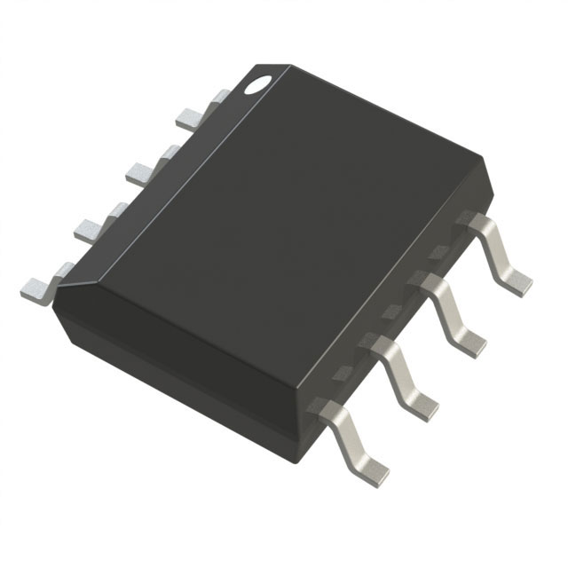
Overview of the EPCS4SI8N Serial Configuration Chip
The EPCS4SI8N is a flexible chip for saving and retrieving data. It is important in systems like cars, factories, and networks that need reliable communication. This chip has 4Mb memory and works with 2.7V to 3.6V power. It can handle temperatures from -40°C to 85°C without problems.
Category | Details |
|---|---|
Memory Size | 4Mb |
Voltage - Supply | 2.7V ~ 3.6V |
Operating Temperature | -40°C ~ 85°C |
Package/Case | SOIC-8 |
Interface | SPI |
Applications | Automotive, Industrial, Networking |
The chip uses an SPI interface for safe communication. It also uses little power and works quickly. These features make it great for systems that need to work well and last long.
Role of SPI in Configuring the EPCS4SI8N
The SPI protocol is key to setting up the EPCS4SI8N. It creates a direct link between the chip and the microcontroller. This link helps them share data easily. In SPI, the microcontroller is the master, and the EPCS4SI8N is the slave.
SPI makes setup easier by letting the master send commands and get responses at the same time. It allows data to flow both ways without stopping, which is important for real-time tasks. Using SPI gives you better control of the chip, helping it work its best.
Benefits of Using the Serial Peripheral Interface
The SPI interface has many advantages when used with the EPCS4SI8N. These include:
High Data Transfer Speeds: SPI sends and receives data quickly, which is great for fast tasks.
Simple Hardware Interface: It needs fewer parts, making it cheaper and easier to use.
Continuous Data Flow: SPI sends and gets data at the same time, improving communication.
Support for Multiple Slaves: One master can control many slaves, useful for big systems.
Low System Overhead: SPI uses less CPU power, saving resources and making software simpler.
Benefit | Description |
|---|---|
High Data Transfer Speeds | Sends and receives data fast, perfect for quick tasks. |
Simple Hardware Interface | Needs fewer parts, making it cheaper and easier to set up. |
Continuous Data Flow | Sends and gets data at the same time, improving communication. |
Support for Multiple Slaves | One master can control many slaves, great for big systems. |
Low System Overhead | Uses less CPU power, saving resources and simplifying software. |
Using SPI ensures the EPCS4SI8N communicates well and works efficiently, making it a great choice for your projects.
Hardware Setup for the EPCS4SI8N Chip
Tools and Parts Needed for Setup
To set up the EPCS4SI8N chip for SPI communication, you need these:
EPCS4SI8N Chip: This chip keeps data safe during SPI communication. It uses a fast SPI interface for quick data transfer.
Microcontroller with SPI: Pick one that supports SPI and matches the chip's voltage.
Power Supply: Use a steady power source between 2.7V and 3.6V.
Clock Signal Generator: Make sure the clock signal is stable and works with SPI.
Wires and Breadboard: These connect the chip to the microcontroller securely.
Oscilloscope or Logic Analyzer: Check signals and fix communication problems with these tools.
Ensure the voltage and clock signal are correct for a successful setup.
Connecting Pins for SPI
To connect the EPCS4SI8N chip to your microcontroller, follow these steps:
Find the SPI Pins: Locate the CS, SCK, MOSI, and MISO pins on the chip.
Attach Power: Connect the VCC pin to 3.3V and GND to ground.
Wire the SPI Pins:
Link the CS pin to a GPIO pin on the microcontroller.
Connect the SCK pin to the microcontroller's SPI clock pin.
Attach the MOSI pin to the microcontroller's SPI output pin.
Connect the MISO pin to the microcontroller's SPI input pin.
Check Connections: Make sure all wires are secure and match the diagram.
Correct wiring is key for stable SPI communication.
Checking the Hardware Setup
After wiring, check the setup to ensure it works properly. Do this:
Look at Connections: Ensure all wires are tight and not loose.
Test Power: Use a multimeter to confirm the chip gets 2.7V to 3.6V.
Check Signals: Use an oscilloscope to see if the clock and data signals are stable.
Run a Test Program: Write a simple program to send and receive data. Check if the chip responds correctly.
By checking everything, you can avoid problems and set up the chip smoothly.
Software Configuration for SPI Protocol
Setting Up the SPI Interface in the Microcontroller
To set up SPI on your microcontroller, turn on its SPI module. Then, adjust the settings to match the EPCS4SI8N chip. First, check the microcontroller's manual or datasheet. Find the section about enabling SPI. Most microcontrollers use registers to control SPI. You need to change these registers to fit the chip's needs.
Here are the main settings to adjust:
Clock Polarity (CPOL): Match this with the clock's idle state for the chip.
Clock Phase (CPHA): Set when data is read and sent.
SPI Clock Speed: Pick a speed the chip supports. Check its datasheet for limits.
Data Order: Choose if the biggest or smallest bit is sent first.
Master/Slave Mode: Make the microcontroller the master to control communication.
After setting these, test them with a simple program. This ensures the SPI is ready to work with the chip.
Writing Code for SPI Communication with the EPCS4SI8N
To write SPI code, start by setting up the SPI interface. Then, create commands for the EPCS4SI8N chip. First, include the SPI library or headers in your code. Next, write functions for setup and data transfer.
Follow these steps:
Set Up SPI: Write a function to set clock speed, polarity, and phase.
Send Commands: Create a function to send commands using the SPI library.
Receive Data: Write a function to get data from the chip using SPI.
Control Chip Select: Add code to manage the CS pin. Pull it low to send data and high when done.
Organizing your code into functions makes it easier to fix and reuse later.
Example Code Snippets for Serial Peripheral Interface
Here’s an example of SPI code for the EPCS4SI8N chip. It uses a basic microcontroller with an SPI library.
#include <SPI.h> // Include the SPI library

#define CS_PIN 10 // Define the chip select pin

void setup() {
  pinMode(CS_PIN, OUTPUT); // Set the CS pin as output
  digitalWrite(CS_PIN, HIGH); // Set CS pin high (inactive)

  SPI.begin(); // Start the SPI interface
  SPI.setClockDivider(SPI_CLOCK_DIV16); // Set clock speed
  SPI.setDataMode(SPI_MODE0); // Set CPOL=0, CPHA=0
  SPI.setBitOrder(MSBFIRST); // Send MSB first
}

void sendCommand(byte command) {
  digitalWrite(CS_PIN, LOW); // Activate the chip
  SPI.transfer(command); // Send the command
  digitalWrite(CS_PIN, HIGH); // Deactivate the chip
}

byte readData() {
  digitalWrite(CS_PIN, LOW); // Activate the chip
  byte data = SPI.transfer(0x00); // Send dummy byte and read response
  digitalWrite(CS_PIN, HIGH); // Deactivate the chip
  return data;
}

void loop() {
  sendCommand(0x9F); // Example command to read chip ID
  byte chipID = readData(); // Read the response
  // Add code to process the chip ID
}
This example shows how to set up SPI, send commands, and read data. Change the commands and settings to fit your project.
Testing and Checking the Setup
Testing makes sure the EPCS4SI8N chip works with SPI. This step checks if your hardware and software are set up right. Follow these steps to test and check your setup:
1. Try a Simple Communication Test
Run a basic program to see if the microcontroller talks to the chip. Use the earlier example code or write a simple script. For example, send a "Read ID" command to check the chip's identity.
What to Expect: The chip should send back its unique ID. If it does, the SPI setup is working.
2. Watch Signals with an Oscilloscope
Use an oscilloscope or logic analyzer to check SPI signals. Look at these:
Clock Signal (SCK): Make sure it’s steady and matches the microcontroller’s settings.
Data Lines (MOSI and MISO): Check that data is sent and received clearly.
Chip Select (CS): Ensure the CS pin switches on and off correctly.
Tip: If signals look wrong, check your wires and microcontroller settings again.
3. Check Data Accuracy
Test if the data sent and received is correct. Write a program to send known data to the chip and read it back. Compare the received data with what you sent.
What to Expect: The data should match perfectly. If it doesn’t, there’s a problem with the SPI setup or signal quality.
4. Test Real-Life Scenarios
Pretend to use the chip like you would in real life. For example:
Save data to the chip and read it back.
Do many read/write tasks to check if it stays stable.
Note: Testing like this helps find problems before using the chip for real.
5. Fix and Improve
If tests fail, use tools to find the problem. Common issues include wrong SPI settings, loose wires, or timing errors. Fix these and test again until everything works.
Reminder: Write down your test results. This helps you remember changes and keeps future setups consistent.
By doing these steps, you can be sure the EPCS4SI8N chip is set up correctly. Good testing ensures smooth and reliable communication in your system.
Troubleshooting Configuration Issues
Fixing Hardware Connection Problems
Problems with hardware connections can stop SPI communication from working. To fix this, check and test all connections carefully. Start by looking at the power and SPI lines. Make sure cables are plugged in tightly and are not damaged. Loose or broken wires often cause issues.
Steps to follow:
Check all connections, including power and SPI/JTAG lines.
Make sure cables are secure and in good shape.
Try different cables or ports to find faulty hardware.
A multimeter can check if connections are working. If a cable seems bad, replace it and test again. These steps help create a strong hardware setup for SPI.
Fixing SPI Communication Problems
If SPI communication fails, you need to debug the problem. Follow these steps to find and fix the issue:
Check the clock signal and timing. Make sure the clock is steady and matches the chip's needs.
Look for loose wires or bad connections in the SPI setup.
Confirm the configuration file is correct for your device.
Test the power supply voltage. It must stay within the right range.
Ensure all pins and cables are connected properly.
Reload a fresh configuration file if memory corruption is suspected.
Update the software and drivers to the latest version.
By following these steps, you can solve most SPI communication problems.
Keeping Timing and Signals Correct
Good timing and clean signals are important for SPI to work well. Bad signals or noise can mess up data. Use an oscilloscope to check if signals meet the needed standards.
Problem Type | What Happens |
|---|---|
Wrong SPI Signals | Devices may not talk to each other correctly. |
Noise | Adds errors to the signal, ruining data. |
Weak Signals | Signals get weaker over long distances, causing issues. |
Clock Frequency Mismatch | Timing problems can cause lost or bad data. |
To avoid these problems, use shielded cables to block noise. Match the clock frequency to the chip's needs. Regularly test signal quality to keep SPI communication strong.
Tips for Finding and Fixing Common Problems
Fixing SPI issues with the EPCS4SI8N chip needs careful steps. Follow these tips to solve common problems:
Check the Clock Signal and Timing
Use an oscilloscope to check the clock signal. Make sure the frequency matches the chip’s needs. Wrong timing can cause errors. Adjust the clock settings in your microcontroller to match the chip.Test SPI Data Flow
Run a simple program to send and receive data. If the chip doesn’t respond, check the MOSI and MISO lines. Loose wires or damaged cables can block communication.Confirm the Configuration File
Ensure the configuration file fits the chip’s setup. A bad or wrong file can cause problems. Reload the file if needed and make sure it works with your system.Check Power Supply
Use a multimeter to measure the voltage at the VCC pin. It should stay between 2.7V and 3.6V. Unsteady power can cause the chip to fail. Replace weak power sources to keep it stable.Inspect the Programming Pins
Look at the JTAG or other programming pins for proper connections. Bad connections can stop the chip from working. Check the pins and make sure the programming tool is working.Fix Flash Memory Issues
If the chip acts strangely, its memory might be damaged. Erase and reprogram the memory using the right tools. This often fixes storage problems.Update Software and Drivers
Old software can cause errors. Install the latest drivers and firmware for your microcontroller. Updates often fix bugs and improve performance.
Tip: Write down what you do while troubleshooting. Keeping notes helps you remember fixes and avoid repeating mistakes.
By following these steps, you can fix SPI problems and make the EPCS4SI8N chip work well.
Setting up the EPCS4SI8N chip for SPI communication needs key steps. First, connect the pins properly and check the power supply. Then, enable the SPI interface and write correct code for it. Testing and fixing issues ensure everything works well.
Tip: Always check your wires and settings carefully. Even small mistakes can cause problems.
To learn more, check these links:
EPCS4SI8N Datasheet
SPI Protocol Basics
Microcontroller SPI Setup Guide
By following these steps and resources, you can make the EPCS4SI8N chip work smoothly and reliably.
FAQ
What does the EPCS4SI8N chip do in SPI communication?
The EPCS4SI8N chip saves setup data and helps devices talk using SPI. It makes sure data moves safely in systems like factories, cars, and networks.
How do you pick the right clock speed for SPI?
Look at the EPCS4SI8N datasheet for its top clock speed. Set your microcontroller's SPI clock below this to keep it steady. For example:
SPI.setClockDivider(SPI_CLOCK_DIV16); // Change if needed
Why is the Chip Select (CS) pin needed in SPI?
The CS pin turns on the EPCS4SI8N chip for talking. Pull it low to make the chip listen. Set it high when done to avoid mixing signals with other devices.
What tools help fix SPI problems?
Use an oscilloscope or logic analyzer to check signals like SCK, MOSI, and MISO. A multimeter can test if the power is steady. These tools find timing issues, noise, or weak signals.
Can the EPCS4SI8N chip work with more than one microcontroller?
No, the EPCS4SI8N chip works as one slave in SPI. Only one master microcontroller can control it at a time. Use extra SPI chips for setups with more masters.
Tip: Always double-check your wires and SPI settings before testing setups with many devices.
See Also
Understanding Specifications of EP4CE6E22C8N Cyclone IV FPGA
Embedded Systems Utilizing XC2C128-7VQG100I Programmable Logic Devices
Essential Information About CP2104-F03-GMR in Embedded Systems
The Importance of CP2108-B02-GMR Silicon in Current Technology